Dum-E
A self-designed robotic arm built entirely from scratch — through four confirmed stages from basic serial control to a WiFi web dashboard and a wearable ESP-NOW glove controller.
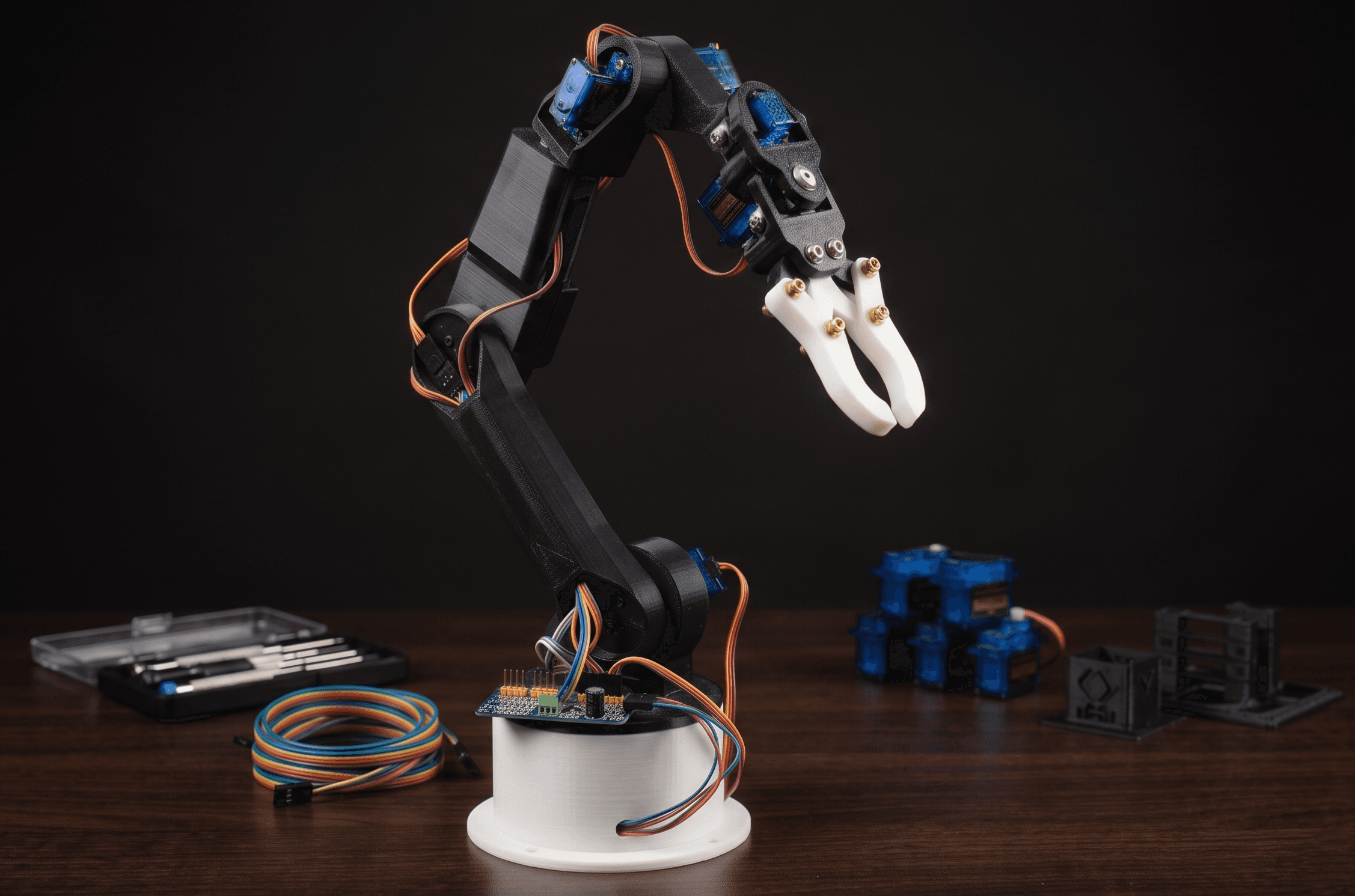
Overview
Dum-E is a personal, self-designed robotic arm built to explore embedded systems, wireless communication, and real-time control — named after the loyal robotic arm from the Iron Man franchise. Unlike typical hobby arm kits, every firmware decision, wiring choice, calibration constant, and software architecture pattern was arrived at through iterative, hardware-in-the-loop testing.
The project is structured in four discrete, confirmed stages. Each stage is fully validated before the next begins — a discipline that ensures a stable, well-understood baseline at every phase of development.
Key Specifications
| Parameter | Value |
|---|---|
| Axes of Motion | 6 |
| Main Controller | XIAO ESP32 S3 |
| Glove Controller | XIAO ESP32 C3 |
| PWM Driver | PCA9685 (I2C, 0x40) |
| PWM Frequency | 60 Hz |
| Power Supply | External 5V, 3A |
| Control Modes | WiFi Web UI, ESP-NOW Glove |
| Communication | WiFi (HTTP), ESP-NOW, I2C |
| IMU | MPU6050 (Pitch + Roll only) |
| Flex Sensors | 2× resistive |
| Firmware Language | C++ (Arduino framework) |
| Motion Architecture | Non-blocking (millis()-based) |
Joint Layout
| Joint | Servo | Channel | Range | Home |
|---|---|---|---|---|
| S1 — Waist | MG995 | CH0 | 0° – 180° | 90° |
| S2 — Shoulder | MG995 | CH1 | 45° – 135° | 90° |
| S3 — Elbow | MG995 | CH2 | 30° – 150° | 90° |
| S4 — Wrist Roll | MG90S | CH3 | 0° – 180° | 90° |
| S5 — Wrist Pitch | SG90 | CH4 | 45° – 135° | 110° |
| S6 — Grip | SG90 | CH5 | 20° – 100° | 60° |
What Makes Dum-E Different
- →No kit dependency. Every subsystem — mechanical, electrical, and software — was independently designed or selected.
- →Stage-by-stage confirmation. Each stage is confirmed fully working before the next begins. When something breaks in a new stage, the root cause search is bounded to what changed.
- →Non-blocking firmware. All six servos move simultaneously using a millis()-based engine, keeping the WiFi server fully responsive during motion.
- →Physically-tuned per-servo motion. Step delay and step size were determined through actual physical testing, not theory, to eliminate stiction on the MG995 joints.
- →Dual-mode glove control. Two motion modes toggled by a single flex sensor, controlling four joints with one IMU and two flex sensors.
- →Confirmed calibration. PWM constants (SERVOMIN=125, SERVOMAX=625) were physically validated once in Stage 1 and have never been recalculated.
Components & Bill of Materials
Main Arm Electronics
| Component | Role | Specs / Notes |
|---|---|---|
| XIAO ESP32 S3 | Main arm controller | Dual-core 240 MHz, WiFi + ESP-NOW, I2C |
| PCA9685 PWM Driver | Servo signal generator | 16-channel, I2C, 0x40, 60 Hz |
| External 5V 3A PSU | Servo power supply | Dedicated; all 6 servos stable at 3A |
| MG995 × 3 | Heavy-duty servos (S1–S3) | 9–11 kg·cm torque, metal gear |
| MG90S × 1 | Mid-weight servo (S4) | Metal gear, lighter than MG995 |
| SG90 × 2 | Light servos (S5, S6) | Plastic gear; wrist pitch and grip |
Glove Controller Electronics
| Component | Role | Specs / Notes |
|---|---|---|
| XIAO ESP32 C3 | Glove microcontroller | ESP-NOW transmitter, compact form factor |
| MPU6050 | 6-axis IMU | Pitch + Roll only — Yaw excluded |
| Flex Sensor × 2 | Finger bend detection | Resistive; voltage divider wired |
| 10 kΩ resistor × 2 | Voltage divider pull-down | Substitute 47 kΩ if ADC delta < 100 |
| LiPo / USB power | Glove power source | Wrist-mounted or tethered |
Software Libraries
| Library | Used For |
|---|---|
| Adafruit PWMServoDriver | PCA9685 I2C control |
| WebServer (ESP32) | WiFi HTTP server on S3 |
| esp_now.h | ESP-NOW transmitter and receiver |
| Wire.h | I2C communication |
| WiFi.h | WiFi stack on S3 |
| MPU6050 library | IMU raw data access on C3 |
Hardware Model
Interactive 3D view of each 3D-printed component. Select a part below to inspect it — drag to rotate, scroll to zoom.
Loading 3D viewer...
Stage 1 — Serial Monitor ControlCompleted
Stage 1 is the foundation. No wireless control, no simultaneous motion — just a rock-solid baseline that proves the hardware stack works and locks in the calibration constants that carry forward permanently. Control is via Arduino Serial Monitor using commands like S1-90 or S1-90, S2-45. Motion is smooth but sequential and blocking.
Hardware: Arduino Uno R3 + PCA9685 PWM driver (I2C, 0x40) + external 5V 3A PSU + all 6 servos. PCA9685 was chosen from the start over onboard PWM pins — it generates stable 60 Hz independently over I2C, keeping servo timing clean regardless of CPU load, and scales forward without hardware changes.
PWM Calibration — The Permanent Constants
SERVOMIN and SERVOMAX are the most important constants in the entire project. Determined physically by commanding each servo to 0° and 180° and observing actual sweep. At these values, no servo buzzed at endpoints and full mechanical range was achieved. These values have never been recalculated since.
#define SERVOMIN 125   // physically validated — never change
#define SERVOMAX 625
#define PWM_FREQ  60   // Hz

int angleToPulse(int angle) {
  return map(angle, 0, 180, SERVOMIN, SERVOMAX);
}
Per-Joint Limits & Home Positions
Each servo's limits were set by physically driving joints to their mechanical boundaries and observing where binding or structural collision occurred. S2 (Shoulder) constrained to 45°–135° to prevent upper-arm binding. S5 (Wrist Pitch) has a home of 110° rather than 90° — correcting a mechanical offset in the wrist assembly geometry that was discovered during physical testing.
// Index 0 unused — servos numbered 1–6
const uint8_t SERVO_CH[7]        = {255,  0,   1,   2,   3,   4,   5  };
const uint8_t SERVO_MIN_ANGLE[7] = {  0,  0,  45,  30,   0,  45,  20 };
const uint8_t SERVO_MAX_ANGLE[7] = {  0,180, 135, 150, 180, 135, 100 };
const uint8_t SERVO_HOME[7]      = {  0, 90,  90,  90,  90, 110,  60 };
Startup Sequence
On boot, all servos are snapped directly to home via raw PWM writes (bypassing the smooth motion engine) before any commands are accepted. A 500 ms gap between each snap prevents simultaneous inrush current from all six servos on cold-start.
void syncAndHome() {
  for (uint8_t i = 1; i <= 6; i++) {
    board1.setPWM(SERVO_CH[i], 0, angleToPulse(SERVO_HOME[i]));
    currentAngle[i] = SERVO_HOME[i];
    delay(500);  // prevents simultaneous inrush current
  }
  homeAllServos();  // smooth confirmation pass
}
Smooth Single-Servo Move
Every commanded move is incremental — the servo steps from its current angle to the target 1°/step with a 35 ms delay, producing a gliding motion rather than a snap. Angle clamping happens once before the loop begins.
void moveServoSmooth(uint8_t servoNum, uint8_t target) {
  uint8_t limited = constrain(target,
                    SERVO_MIN_ANGLE[servoNum],
                    SERVO_MAX_ANGLE[servoNum]);
  float current = currentAngle[servoNum];

  while ((int)current != (int)limited) {
    if (current < limited) current += STEP_SIZE;
    else                   current -= STEP_SIZE;
    current = constrain(current,
              SERVO_MIN_ANGLE[servoNum], SERVO_MAX_ANGLE[servoNum]);
    board1.setPWM(SERVO_CH[servoNum], 0, angleToPulse((int)current));
    delay(STEP_DELAY_MS);  // 35 ms global — per-servo tuning comes in Stage 2
  }
  currentAngle[servoNum] = limited;
}
Stage 1 Challenges
Stage 2 — Motion Engine (V1 → V2)Completed
Stage 2 is the largest architectural leap in the project. Everything about how the arm moves changes here. Stage 1 proved the hardware worked; Stage 2 makes it move well. Two firmware versions were developed in sequence — V1 introduces per-servo tuning and conservative simultaneous motion; V2 removes all restrictions and achieves full 6-servo simultaneous movement.
Hardware Changes
The Arduino Uno is replaced by the XIAO ESP32 S3 — not because WiFi is used yet, but to contain the controller migration here rather than mid-Stage 3 when it would complicate debugging.
| Component | Stage 1 | Stage 2 |
|---|---|---|
| Microcontroller | Arduino Uno R3 | XIAO ESP32 S3 |
| I2C Pins (SDA/SCL) | A4 / A5 (default Uno) | D4/GPIO6, D5/GPIO7 — explicitly declared |
| PWM Driver | PCA9685 @ 0x40 | PCA9685 @ 0x40 (unchanged) |
| PWM Calibration | SERVOMIN=125, SERVOMAX=625 | Same — never recalculated |
| Servo Hardware | MG995×3, MG90S×1, SG90×2 | Same 6 servos (unchanged) |
| Serial Baud Rate | 9600 | 9600 (upgraded to 115200 in Stage 3) |
The Core Problem — MG995 Stiction
When the initial simultaneous motion prototype used Stage 1's uniform 35 ms delay, the MG995 servos (S1, S2, S3) jerked in visible discrete steps rather than gliding. The root cause is counterintuitive:
Too long a delay: The servo fully settles between PWM updates. The next update arrives from "rest" — static friction (stiction) must be overcome again. Result: discrete visible lurches.
Too short a delay: PWM updates arrive faster than the servo's internal feedback loop. Overshoot and correction repeatedly. Result: buzzing.
Correct delay: Updates arrive frequently enough that the motor never fully settles — it's always in motion, just slowly guided. Static friction is never re-engaged. Result: smooth glide.
This insight — that the PWM update rate directly controls whether the servo is fighting stiction or flowing through it — is the core discovery of Stage 2 and shaped every subsequent stage.
Per-Servo Tuning Constants
// Index 0 unused — confirmed through physical iteration
const uint8_t STEP_DELAY[7] = {0,  40,  30,  30,  25,  25,  25};
const float   STEP_SIZE[7]  = {0, 1.0, 0.5, 0.5, 1.0, 1.0, 1.0};

// S1 (Waist, MG995):   40 ms / 1.0° — heavier base needs slightly slower updates
// S2 (Shoulder, MG995): 30 ms / 0.5° — fine control for load-bearing lift joint
// S3 (Elbow, MG995):   30 ms / 0.5° — same reasoning as S2
// S4–S6 (lighter):     25 ms / 1.0° — faster and more responsive
The finer 0.5°/step on S2 and S3 produces more intermediate PWM positions during load-bearing moves, keeping the motor continuously guided rather than snapping between widely-spaced targets under torque.
V1 — Conservative Simultaneous Motion
V1 introduces simultaneous motion but only for the three lighter servos (S4, S5, S6). MG995 servos still move sequentially with 100 ms settling delays between each, based on concern about the 3A supply handling three MG995s simultaneously. An IS_MG995[] flag classifies each servo and separates commands into heavy/light groups before dispatch.
void moveSimultaneous(Move* moves, uint8_t count) {
  // Reject MG995 servos — fall back to sequential
  for (uint8_t i = 0; i < count; i++) {
    if (IS_MG995[moves[i].servo]) {
      for (uint8_t j = 0; j < count; j++)
        moveServoSmooth(moves[j].servo, moves[j].target);
      return;
    }
  }

  bool anyActive = true;
  while (anyActive) {
    anyActive = false;
    for (uint8_t i = 0; i < count; i++) {
      uint8_t s = moves[i].servo;
      if ((int)current[i] == (int)limited[i]) continue;
      if (current[i] < limited[i]) current[i] += STEP_SIZE[s];
      else                         current[i] -= STEP_SIZE[s];
      board1.setPWM(SERVO_CH[s], 0, angleToPulse((int)current[i]));
      if ((int)current[i] != (int)limited[i]) anyActive = true;
    }
    delay(25);  // fixed — SG90/MG90S safe rate
  }
}
V2 — Full Simultaneous Motion
V1's restriction was physically tested: three MG995s commanded simultaneously — no brownout, no reset. The 3A supply proved adequate. V2 removes IS_MG995[] entirely. All servos move simultaneously. A key improvement: the tick delay is now dynamically calculated as the maximum STEP_DELAY among active servos — slower servos set the shared tick rate, and as faster servos complete and drop out, the rate naturally decreases.
void moveSimultaneous(uint8_t* servos, uint8_t* targets, uint8_t count) {
  // ... initialise current[], limited[], done[] ...

  bool anyActive = true;
  while (anyActive) {
    anyActive = false;

    // Tick at the slowest rate among still-active servos
    uint8_t tickDelay = 0;
    for (uint8_t i = 0; i < count; i++) {
      if (!done[i] && STEP_DELAY[servos[i]] > tickDelay)
        tickDelay = STEP_DELAY[servos[i]];
    }

    for (uint8_t i = 0; i < count; i++) {
      if (done[i]) continue;
      uint8_t s = servos[i];
      if (current[i] < limited[i]) current[i] += STEP_SIZE[s];
      else                         current[i] -= STEP_SIZE[s];
      board1.setPWM(SERVO_CH[s], 0, angleToPulse((int)current[i]));
      if ((int)current[i] == (int)limited[i]) done[i] = true;
      else anyActive = true;
    }
    delay(tickDelay);  // dynamic — decreases as faster servos complete
  }
}
V2 also tightened some angle limits after continued physical testing (S2 narrowed to 60°–120° after binding observed; S3 expanded to 20°–160° after structure was adjusted) and moved the S6 Grip home to 30°.
Stage 2 Challenges
Stage 3 — WiFi Web DashboardCompleted
Stage 3 is where Dum-E becomes a network device. The XIAO ESP32 S3 connects to WiFi, starts an HTTP server on port 80, and serves a complete control interface to any browser on the same network. No USB cable or Serial Monitor needed — any phone or laptop on the same WiFi can open the IP address and control all six joints.
Stage 3 also solves the fundamental blocking problem from Stage 2. The motion engine is fully rewritten to be non-blocking using millis()-based timing. Both the HTTP server and servo stepping run concurrently in the same loop() with neither blocking the other.
Wiring — PCA9685 → XIAO ESP32 S3
| PCA9685 Pin | Connects To | Notes |
|---|---|---|
| SDA | D4 (GPIO 6) | I2C data |
| SCL | D5 (GPIO 7) | I2C clock |
| VCC | 3.3V | Logic power from S3 |
| GND | GND | Common ground |
| V+ | 5V external PSU | Servo power — separate from logic supply |
Access the web UI at http://<IP printed to Serial Monitor on boot> from any device on the same WiFi network.
The Core Architectural Shift — Non-Blocking Motion
The entire blocking while loop from Stage 2 is gone. Replaced by a ServoState struct and a stepServos() function that advances one step per servo per loop() call — no delay() anywhere.
struct ServoState {
  float    current;   // actual position (float for sub-degree stepping)
  uint8_t  target;    // desired destination
  uint32_t lastStep;  // millis() timestamp of last step
};
ServoState sv[7]; // index 1–6// Called on every single loop() iteration — never blocks
void stepServos() {
uint32_t now = millis();
for (uint8_t s = 1; s <= 6; s++) {
if ((int)sv[s].current == (int)sv[s].target) continue; // already there
if (now - sv[s].lastStep < STEP_DELAY[s]) continue; // not time yet
if (sv[s].current < sv[s].target) sv[s].current += STEP_SIZE[s];
else sv[s].current -= STEP_SIZE[s];
sv[s].current = constrain(sv[s].current,
SERVO_MIN_ANGLE[s], SERVO_MAX_ANGLE[s]);
board1.setPWM(SERVO_CH[s], 0, angleToPulse((int)sv[s].current));
sv[s].lastStep = now;
}
}
// The entire main loop
void loop() {
server.handleClient(); // handle incoming HTTP — returns immediately if nothing pending
stepServos(); // advance any due servos — returns immediately
// Neither ever blocks. HTTP server is always responsive, even during motion.
}HTTP Server — 5 Routes
| Route | Parameters | Action |
|---|---|---|
| GET / | None | Serves full web UI HTML from PROGMEM |
| GET /move?s=N&a=A | s=servo, a=° | Sets sv[s].target — returns immediately |
| GET /home | None | Sets all 6 targets to home angles |
| GET /stop | None | Sets each target to current position (freeze) |
| GET /status | None | Returns JSON of all current angles |
// setTarget() — the ONLY write path for target angles
void setTarget(uint8_t s, uint8_t angle) {
  if (s < 1 || s > 6) return;
  sv[s].target = constrain(angle, SERVO_MIN_ANGLE[s], SERVO_MAX_ANGLE[s]);
}

// /stop — freeze wherever the arm currently is
void handleStop() {
  for (uint8_t i = 1; i <= 6; i++)
    sv[i].target = (uint8_t)sv[i].current;  // target = current → stepServos() stops
  server.send(200, "text/plain", "OK");
}

// /status — returns ground-truth positions as JSON
void handleStatus() {
  String json = "{";
  for (uint8_t i = 1; i <= 6; i++) {
    json += "\"s" + String(i) + "\":" + String((int)sv[i].current);
    if (i < 6) json += ",";
  }
  json += "}";
  server.send(200, "application/json", json);
  // e.g.: {"s1":90,"s2":73,"s3":90,"s4":45,"s5":110,"s6":60}
}
Web UI Deep Dive
The entire web UI is a self-contained HTML/CSS/JS page stored in PROGMEM using Arduino's raw string literal syntax and served via server.send_P() — reads directly from flash without copying to SRAM, preserving heap for the HTTP and WiFi stacks.
// Each servo's physical range — not a generic 0–180° slider
const SERVOS = [
  { id:1, name:'Waist',       min:0,   max:180, home:90  },
  { id:2, name:'Shoulder',    min:45,  max:135, home:90  },
  { id:3, name:'Elbow',       min:30,  max:150, home:90  },
  { id:4, name:'Wrist Roll',  min:0,   max:180, home:90  },
  { id:5, name:'Wrist Pitch', min:45,  max:135, home:110 },
  { id:6, name:'Grip',        min:20,  max:100, home:60  },
];const lastSend = {};
function sendMove(servo, angle) {
const now = Date.now();
if (lastSend[servo] && now - lastSend[servo] < 50) return; // 20 req/s max
lastSend[servo] = now;
fetch('/move?s=' + servo + '&a=' + angle).catch(() => {});
}
// Final send on slider release — guarantees last angle always reaches firmware
sl.addEventListener('change', () => sendMove(s.id, +this.value));// Keeps UI in sync regardless of which input moved the arm
setInterval(() => {
fetch('/status')
.then(r => r.json())
.then(d => {
for (let i = 1; i <= 6; i++) {
const a = d['s' + i];
if (a === undefined) continue;
// Don't override a slider the user is actively dragging
if (document.activeElement !== sliders[i]) {
sliders[i].value = a;
labels[i].innerHTML = a + '<span class="unit">°</span>';
}
}
}).catch(() => {});
}, 500);The 500 ms status poll is the key forward-looking design decision: when Stage 4's glove controller moves a servo via ESP-NOW without the browser knowing, the browser will still reflect the correct arm state automatically.
Stage 3 Challenges
Stage 4 — ESP-NOW Glove ControllerIn Progress
Stage 4 introduces a wearable glove controller as the second input modality. The glove uses an MPU6050 IMU for hand orientation (Pitch and Roll) and two resistive flex sensors for finger bend detection. All sensor data is packed into a struct and broadcast over ESP-NOW every loop cycle from the XIAO ESP32 C3 on the glove to the XIAO ESP32 S3 on the arm.
On the arm side, an ESP-NOW receive callback fires on every incoming packet, decodes the struct, and routes each field to the appropriate sv[s].target — feeding directly into the same stepServos() engine that the web UI already uses. Both control inputs share the same motion engine with no conflict.
Glove Hardware Stack
| Component | Role | Notes |
|---|---|---|
| XIAO ESP32 C3 | Glove MCU — ESP-NOW transmitter | Single-core, WiFi, compact form factor |
| MPU6050 | 6-axis IMU — hand orientation | Pitch + Roll only — Yaw excluded (see Challenges) |
| Flex Sensor 1 (A0) | Grip control — always S6 | Resistive; 10 kΩ voltage divider |
| Flex Sensor 2 (A1) | Mode toggle — ARM vs WRIST | Threshold-based binary state |
#define FLEX1_PIN  A0   // Flex 1 → S6 Grip (always)
#define FLEX2_PIN  A1   // Flex 2 → mode switch

analogReadResolution(12);        // 12-bit → 0 to 4095
analogSetAttenuation(ADC_11db);  // full 3.3V input range
// 12-bit gives ~0.8 mV/count — sufficient for flex bend detection
System Architecture
Glove Controller
XIAO ESP32 C3
- →MPU6050 → Pitch, Roll (comp. filter)
- →Flex 1 → S6 Grip control
- →Flex 2 → Mode Toggle (ARM/WRIST)
- →Pack glove_data struct
Browser Dashboard
Any Device (WiFi)
- →Per-servo sliders (correct range)
- →HOME / STOP buttons
- →500 ms /status poll
- →Reflects glove moves automatically
Main Arm Controller
XIAO ESP32 S3
- →ESP-NOW RX → decode struct → setTarget()
- →HTTP server → slider /move → setTarget()
- →stepServos() → millis() tick → advance current
- →I2C → PCA9685 → PWM → Servos
PCA9685 PWM Driver
16-channel — 60 Hz
- →CH0 → S1 Waist (MG995)
- →CH1 → S2 Shoulder (MG995)
- →CH2 → S3 Elbow (MG995)
- →CH3 → S4 Wrist Roll (MG90S)
- →CH4 → S5 Wrist Pitch (SG90)
- →CH5 → S6 Grip (SG90)
Both the ESP-NOW callback and the HTTP handler write to the same sv[].target array. Whichever wrote last determines where the arm moves. In practice the web UI handles Waist (S1) and monitoring; the glove controls the other joints.
Sensor-to-Servo Mapping
The mapping was designed on paper before a single line of transmitter or receiver firmware was written. Constraints: 1 IMU (Pitch + Roll), 2 flex sensors, 5 joints to control (S2–S6), S1 Waist reserved for web UI. A naive 1:1 mapping covers only 4 joints. Solution: repurpose Flex 2 as a binary mode toggle.
WRIST Mode
Flex 2 straight
- → IMU Pitch → S5 Wrist Pitch
- → IMU Roll → S4 Wrist Roll
- → Flex 1 → S6 Grip (always)
ARM Mode
Flex 2 bent
- → IMU Pitch → S2 Shoulder
- → IMU Roll → S3 Elbow
- → Flex 1 → S6 Grip (always)
S1 (Waist) is intentionally excluded from glove control. Waist rotation is a coarse, full-range sweep. Mapping it to IMU Roll in ARM mode would conflict with the Elbow mapping. Precise waist positioning benefits more from a slider than from tilt — easier to dial in a specific bearing with a slider than to hold the glove at a precise yaw.
void onGloveData(const uint8_t *mac, const uint8_t *data, int len) {
  glove_data packet;
  memcpy(&packet, data, sizeof(packet));

  bool armMode = (packet.flex2_value > FLEX2_THRESHOLD);

  if (armMode) {
    setTarget(2, mapAngle(packet.pitch, PITCH_MIN, PITCH_MAX, 45, 135));  // S2 Shoulder
    setTarget(3, mapAngle(packet.roll,  ROLL_MIN,  ROLL_MAX,  30, 150));  // S3 Elbow
  } else {
    setTarget(5, mapAngle(packet.pitch, PITCH_MIN, PITCH_MAX, 45, 135));  // S5 Wrist Pitch
    setTarget(4, mapAngle(packet.roll,  ROLL_MIN,  ROLL_MAX,   0, 180));  // S4 Wrist Roll
  }
  // Grip: always Flex 1, always S6
  setTarget(6, mapAngle(packet.flex1_value, FLEX1_STRAIGHT, FLEX1_BENT, 20, 100));
}
Why ESP-NOW
ESP-NOW was selected after direct experience with Bluetooth instability (HC-05/HC-06 connection drops under servo current load in a related college project).
| Property | ESP-NOW | Bluetooth Serial (HC-05/HC-06) |
|---|---|---|
| Pairing required | No — peer MAC address only | Yes — pairing sequence required |
| Latency | ~1–3 ms | 10–30 ms typical |
| Router dependency | None | None (direct link) |
| Native ESP32 support | Yes — esp_now.h | No — external UART module |
| Reliability | Connectionless — no session to drop | Session-based — can drop under interference |
The S3's MAC address is read from Serial output once during initial setup and hardcoded into the C3 transmitter sketch. One-time configuration, not a runtime pairing process.
Flex Calibration — Deep Dive
Before any transmitter firmware can map flex sensor readings to servo angles, the ADC range of each sensor must be measured in the actual wired glove. Resistive flex sensors vary significantly between units — even the same nominal sensor from the same batch can have very different absolute resistance values depending on manufacturing tolerances. Hardcoding ADC values without per-unit calibration would produce wildly incorrect angle mappings.
The solution is a dedicated standalone calibration sketch that runs on the C3 before the transmitter firmware is ever flashed. It exposes an interactive Serial menu — the user types a letter, holds a pose, and the sketch records the averaged ADC reading for that position.
// Runs standalone on XIAO ESP32 C3 at 115200 baud
// ========================================
//   Dum-E — Flex Sensor Calibration
// ========================================
//   R  — Read raw ADC values (live)
//   1  — Calibrate Flex1 STRAIGHT
//   2  — Calibrate Flex1 BENT
//   3  — Calibrate Flex2 STRAIGHT
//   4  — Calibrate Flex2 BENT
//   T  — Test mapped angles live
//   S  — Show calibration values
//   H  — Show this menu
// ========================================
The ESP32's ADC is known to be noisy — single readings fluctuate by tens of counts even on a stable input. A single-sample calibration would lock in a noisy value. The fix is to average 20 samples with small gaps between each, producing a stable representative value.
// 20-sample average with 2 ms gaps — reduces ESP32 ADC noise
#define NUM_SAMPLES 20

int readADC(uint8_t pin) {
  long sum = 0;
  for (int i = 0; i < NUM_SAMPLES; i++) {
    sum += analogRead(pin);
    delay(2);
  }
  return (int)(sum / NUM_SAMPLES);
}
Each calibration step follows the same pattern: print a prompt, wait 2 seconds for the user to settle into the correct pose (straight or fully bent), then take an averaged ADC reading. The 2-second pause eliminates motion transients from the sample — without it, the reading would capture the sensor mid-bend rather than at its true endpoint.
// Each step: 2s wait for user to hold pose still, then averaged ADC read
case '1': {
  Serial.println(F("[CAL] Hold Flex1 finger STRAIGHT"));
  Serial.println(F("[CAL] Keep still... sampling in 2s"));
  delay(2000);  // user settles into pose; eliminates motion transients
  flex1_straight = readADC(FLEX1_PIN);
  Serial.print(F("[CAL] Flex1 STRAIGHT = "));
  Serial.println(flex1_straight);
  break;
}
Flex 2 is special — it's not used as a continuous control input but as a binary mode toggle. Rather than mapping its full ADC range to an angle, the sketch calculates a single threshold value: the midpoint between the straight and bent readings. A reading above this threshold means ARM Mode; below means WRIST Mode. Using the midpoint gives equal hysteresis distance in both directions, reducing the chance of accidental mode switches near the boundary.
// Mode toggle threshold: midpoint between straight and bent ADC values
case '4': {
  delay(2000);
  flex2_bent = readADC(FLEX2_PIN);
  flex2_calibrated = true;

  int threshold = (flex2_straight + flex2_bent) / 2;  // symmetric hysteresis
  Serial.print(F("[CAL] Mode switch threshold = "));
  Serial.println(threshold);
  break;
}
After all four readings are captured, command T streams live angle-mapped output to Serial at 5 Hz. This is the critical human verification step before the transmitter sketch is ever flashed — the user physically bends each finger and confirms the correct joint angle changes in the Serial output. They also flex Flex 2 to confirm the MODE label switches between ARM and WRIST. If mode doesn't switch, the threshold comparison direction may need to be inverted — noted in the code.
// Human verification step before flashing transmitter sketch
case 'T': {
  int threshold = (flex2_straight + flex2_bent) / 2;
  while (!Serial.available()) {
    int f1 = readADC(FLEX1_PIN);
    int f2 = readADC(FLEX2_PIN);
    int s6angle = adcToAngle(f1, flex1_straight, flex1_bent, 20, 100);
    bool armMode = (f2 > threshold);
    Serial.print(F("  S6: "));  Serial.print(s6angle);
    Serial.print(F("°   Mode: ")); Serial.print(armMode ? F("ARM  ") : F("WRIST"));
    Serial.print(F("   [F1:")); Serial.print(f1);
    Serial.print(F(" F2:"));    Serial.print(f2);
    Serial.println(F("]"));
    delay(200);
  }
  break;
}
Once all four values are confirmed via the live test, command S prints the complete set of constants in a format ready to paste directly into the transmitter sketch header. The main transmitter firmware contains no hardcoded ADC values — it only references these defines. Any Dum-E build with different sensors just runs this calibration sketch once and pastes the output.
// Ready-to-paste #define constants for the transmitter sketch
case 'S': {
  int threshold = (flex2_straight + flex2_bent) / 2;
  Serial.println(F("  PASTE THESE INTO STAGE 4 CODE:"));
  Serial.print(F("  #define FLEX1_STRAIGHT  ")); Serial.println(flex1_straight);
  Serial.print(F("  #define FLEX1_BENT       ")); Serial.println(flex1_bent);
  Serial.print(F("  #define FLEX2_STRAIGHT  ")); Serial.println(flex2_straight);
  Serial.print(F("  #define FLEX2_BENT       ")); Serial.println(flex2_bent);
  Serial.print(F("  #define FLEX2_THRESHOLD  ")); Serial.println(threshold);
  // Example output:
  //   #define FLEX1_STRAIGHT  1240
  //   #define FLEX1_BENT       3180
  //   #define FLEX2_THRESHOLD  2100
  break;
}
The angle mapping function deserves attention: depending on how the flex sensor is physically wired in the glove, the ADC value might increase when the finger is straight and decrease when bent — or vice versa. A naive map() call would produce inverted angles if adcMin is greater than adcMax. The safe version handles both orientations automatically using min() and max() to compute the correct clamp bounds regardless of direction.
// Handles the case where adcMin > adcMax (sensor wired in reverse orientation)
int adcToAngle(int raw, int adcMin, int adcMax, int angleMin, int angleMax) {
  raw = constrain(raw, min(adcMin, adcMax), max(adcMin, adcMax));
  return map(raw, adcMin, adcMax, angleMin, angleMax);
}
Firmware in Development
// Complementary filter: gyro-dominant with slow accel drift correction
void computeComplementaryFilter(float *pitch, float *roll) {
  float dt = (millis() - lastFilterTime) / 1000.0;
  lastFilterTime = millis();
  float accelPitch = atan2(ay, az) * RAD_TO_DEG;
  float accelRoll  = atan2(ax, az) * RAD_TO_DEG;
  *pitch = 0.96 * (*pitch + gx * dt) + 0.04 * accelPitch;
  *roll  = 0.96 * (*roll  + gy * dt) + 0.04 * accelRoll;
  // α=0.96 → τ≈0.24s: fast enough to prevent drift, slow enough for stability
}

void loop() {
  computeComplementaryFilter(&glovePacket.pitch, &glovePacket.roll);
  glovePacket.flex1_value = readADC(FLEX1_PIN);
  glovePacket.flex2_value = readADC(FLEX2_PIN);
  esp_now_send(s3_mac_address, (uint8_t*)&glovePacket, sizeof(glovePacket));
  // glove_data packet: 2 floats + 2 ints = 16 bytes. ESP-NOW max: 250 bytes.
}
Stage 4 Challenges & Design Decisions
Current Progress
Results & Status
Stages 1–3 are fully confirmed working. Stage 4 hardware is assembled and calibration tooling is complete; transmitter firmware is in active development.
What Full Stage 4 Completion Delivers
- →WRIST Mode: physical wrist tilt controls S4 (Wrist Roll) and S5 (Wrist Pitch) in real time
- →ARM Mode: tilting the forearm forward/back controls S2 (Shoulder); side tilt controls S3 (Elbow)
- →Grip: curling Flex 1 opens and closes S6 continuously
- →Mode switch: bending Flex 2 switches all mappings in under one packet cycle (~2 ms)
- →Simultaneous web UI: browser continues to reflect all positions via 500 ms polling even as glove controls them
- →Web UI retains S1 (Waist): slider control unaffected by glove input
What I Learned
- →
Adding a web server to a blocking motion loop kills the server completely — requests just time out while a servo is moving. I had to rebuild the entire motion engine around millis() to fix it, which was more work mid-project than it would have been to design it that way from the start.
- →
The arm doesn't know where it is — only the firmware's currentAngle[] does. If those two ever diverge (which they will on cold boot if you don't handle it), the first command causes a violent snap to wherever the arm thinks it should be. The startup snap sequence exists entirely to prevent that.
- →
Once you physically validate PWM calibration constants, don't touch them again. SERVOMIN and SERVOMAX have been the same since Stage 1. Recalibrating is how you introduce regressions, not improvements.
- →
The stiction problem on MG995 servos surprised me most. I expected smoother to mean slower — but it's the opposite. Update PWM too infrequently and the motor fully settles between steps, then has to break static friction each time. It lurches. Update frequently enough and it never settles — it just flows. Finding that sweet spot per-servo through physical testing was the most hands-on debugging I did.
- →
Checking sensor drift on the MPU6050 before writing any control code saved a lot of time. Yaw drifts badly without a magnetometer — I caught that early and removed it from the design before a single line of yaw-based firmware was written.
- →
The complementary filter handles Pitch and Roll better than I expected for something so simple. I was going to use a Kalman filter, but the complementary filter is stable enough for human-speed arm control and takes about ten lines of code.
- →
When a flex sensor shows less than 100 ADC counts between straight and fully bent, it's almost never the sensor — it's the wiring. Bad solder joint, wrong resistor value, something like that. I learned to check the circuit first before assuming the sensor is broken.
- →
Drawing out the sensor-to-servo mapping on paper before writing any transmitter code made the firmware straightforward. The two-mode glove design came from constraints on paper, not from debugging firmware.
- →
ESP-NOW is genuinely good. No pairing, no router, ~2 ms round trip. Bluetooth had been unreliable in a previous project under servo load, so I switched — and it just works.
- →
Finishing each stage completely before starting the next one saved me a lot of debugging. When something broke in Stage 3, I knew it was a Stage 3 problem. The search space was small.
- →
Datasheets don't capture mechanical reality. STEP_DELAY values, joint limits, home positions — all of them came from looking at and listening to the arm, not from any calculation.
- →
Cutting yaw cleanly was the right call. The decision took five minutes. I didn't try to work around it or replace it with something equivalent. Knowing when to just remove scope is a skill.